
Thermowell unsupported length and insertion length explained
Identify the support plane, distinguish unsupported and shielded length, and check the drawing dimensions before entering a thermowell wake frequency calculation.
By Wake Frequency Calculator · Published 2026-10-16
Educational overview; not engineering design advice.
What is thermowell unsupported length?
Unsupported length is the distance from the thermowell tip to the support plane used for the calculation. In Wake Frequency Calculator, this is the geometry input labelled “Unsupported length - ASME L (mm)”. Confirm those two reference points on the drawing before entering a value.
An insertion or U dimension may measure the same distance, but the letter alone does not establish that. Overall manufactured length, sensor stem length and the length exposed to the fluid can measure different things.
How does it differ from insertion length?
Insertion length describes how far the thermowell extends from a stated connection reference towards its tip. Manufacturers define that reference on their own drawings. Ashcroft, for example, describes a U length from the process connection to the tip and distinguishes it from the instrument insertion length. [1]
Use a supplier’s U dimension for the app’s unsupported length only after confirming that its endpoints coincide with the tip and the applicable support plane. Do not substitute the insertion length of the thermometer, RTD or thermocouple that fits inside the thermowell.
Read the support plane and flow shielding separately
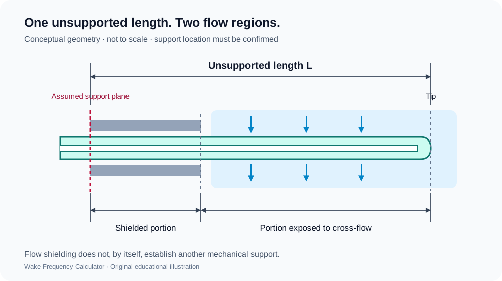
The diagram shows a conceptual support plane, a shielded portion and a portion exposed to cross-flow. It illustrates the terms only; the position and effectiveness of a real support must be established for the proposed connection and installation.
In the app, shielded length is the portion of the unsupported length protected from cross-flow by the installation. It is a separate input. A nozzle can shield part of a stem from flow without establishing a new mechanical support at the nozzle opening.
What should you check on the drawing?
First identify the thermowell tip and the support plane appropriate to the selected connection. Then find the dimension between those points and check its units. Do not take the support plane from a generic picture when the actual drawing or installation establishes a different arrangement.
Next identify any section shielded from cross-flow and keep that measurement separate. Record where each dimension starts and ends. If the drawing does not establish the required reference points, resolve them with the supplier or responsible engineer before treating the inputs as confirmed.
Check the remaining geometry on the same drawing: support or root diameter, tip diameter, bore and tip thickness, plus any profile-specific dimensions. A correct length does not resolve an incorrect diameter or connection.
Can a support collar reduce the unsupported length?
Do not shorten the entered unsupported length merely because the drawing includes a collar. Its contact and restraint cannot be inferred from its appearance. WIKA’s technical guidance discusses the limitations of treating support collars as rigid support and notes the need for an interference fit in the arrangement it describes. [2]
Ask the responsible engineer to establish whether the proposed support and calculation method are applicable. A geometry entry cannot make an unsupported method valid.
How should you enter the length in the calculator?
Select the actual connection and stem profile. Enter the confirmed tip-to-support-plane distance in the unsupported-length field, using the units shown. Enter shielding separately where the workflow requires it; do not reduce unsupported length to the exposed portion.
Read the calculation outcome together with its engineering-readiness status. If a dimension changes, rerun the complete assessment and preserve the drawing revision with the report. Do not alter a real process condition simply to produce a passing result.
Does a shorter thermowell always solve a failed calculation?
Length is one part of the design basis. A revised geometry can change several checks and may affect the intended temperature-measurement installation. Start with the governing check and review an appropriate revision with the responsible engineer.
A calculated PASS applies to the performed checks, inputs and selected method. It does not by itself approve the manufactured assembly or installation.
Sources
- Ashcroft: How to calculate thermowell stem length for temperature instruments
Accessed 2026-10-16. Manufacturer-specific insertion, lagging and instrument-stem terminology; not a universal support-plane definition or endorsement of this app.
- WIKA: Wake frequency calculation, technical information IN 00.15
Accessed 2026-10-16. Discussion of support collars and interference-fit limitations on page 4; not an approval of a particular installation.